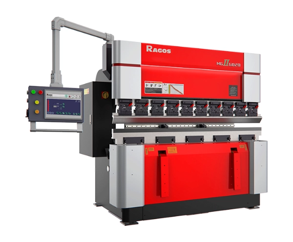
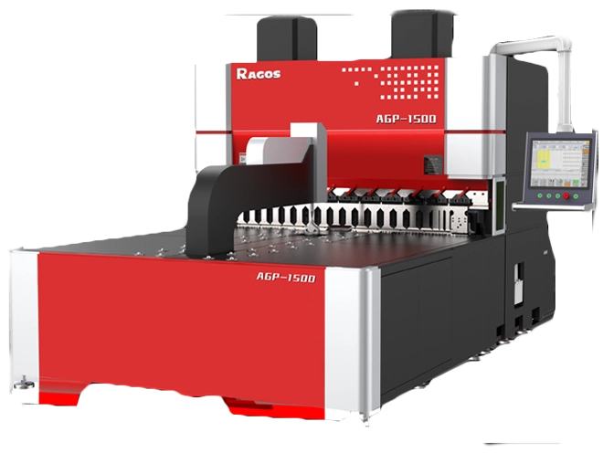

Guide pour débutants: Frein à pression CNC pour la fabrication de métaux
Un frein à pression CNC plie la tôle avec une précision stable. La CNC aligne les jauges de reculement et les outils. Le mouvement de la mise à la puce crée chaque angle. Ce guide présente la sélection des outils, a clear bend order, and reliable quality checks. It addresses typical shop-floor issues and how to avoid them. You will see how careful punch and die selection reduces interference, controls springback, and protects finishes while raising throughput.
Tooling Fundamentals for CNC Press Brake for Metal Fabrication
JS RAGOS recommends starting with tooling discipline. The right punch and die prevent collisions, reduce marking, and stabilize angles. Beginner teams should understand punch construction, tip geometry, and V-groove selection before running production.
- Punch Choices for Beginners
Integral punches support high stability and quick setup. Common integral lengths are 415 mm and 835 mm. Split punches add flexibility for short flanges and complex parts. Typical split segments include 10, 15, 20, 40, 50, 100 (left horn), 100 (right horn), 200, et 300 mm. You can combine segments to match the bending length and avoid gaps.
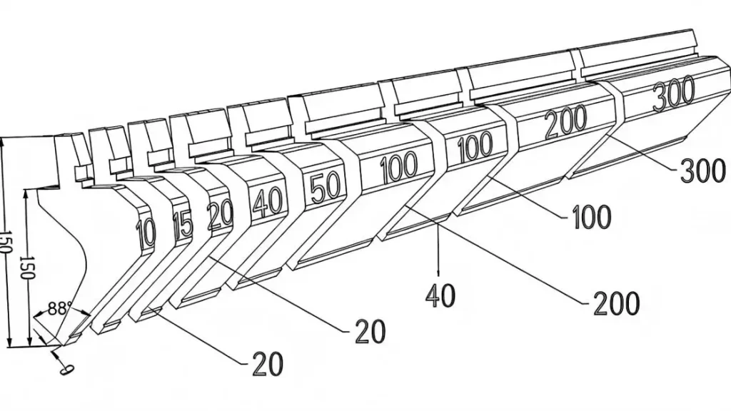
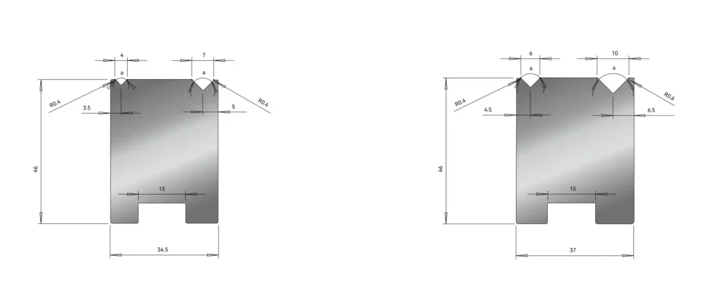
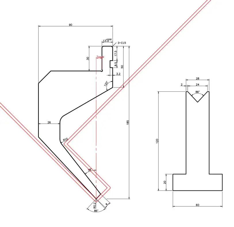
Punch types cover straight, pliage, arc, and special profiles. A straight punch with an 88° tip and tip radius R0.2 offers tight openings and crisp flanges. It is suitable for symmetric parts and small opening widths. Small-angle punches, such as 30° or 45° tips with a tip radius around R0.67, allow clearance around holes, studs, and bosses. They also help deep insert operations and reduce collision risk when the flange is short.
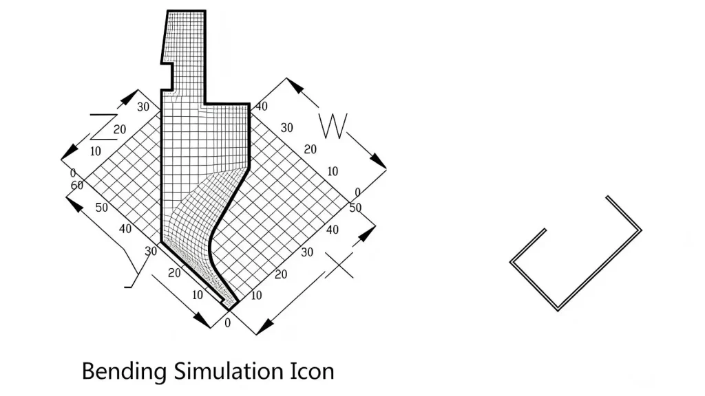
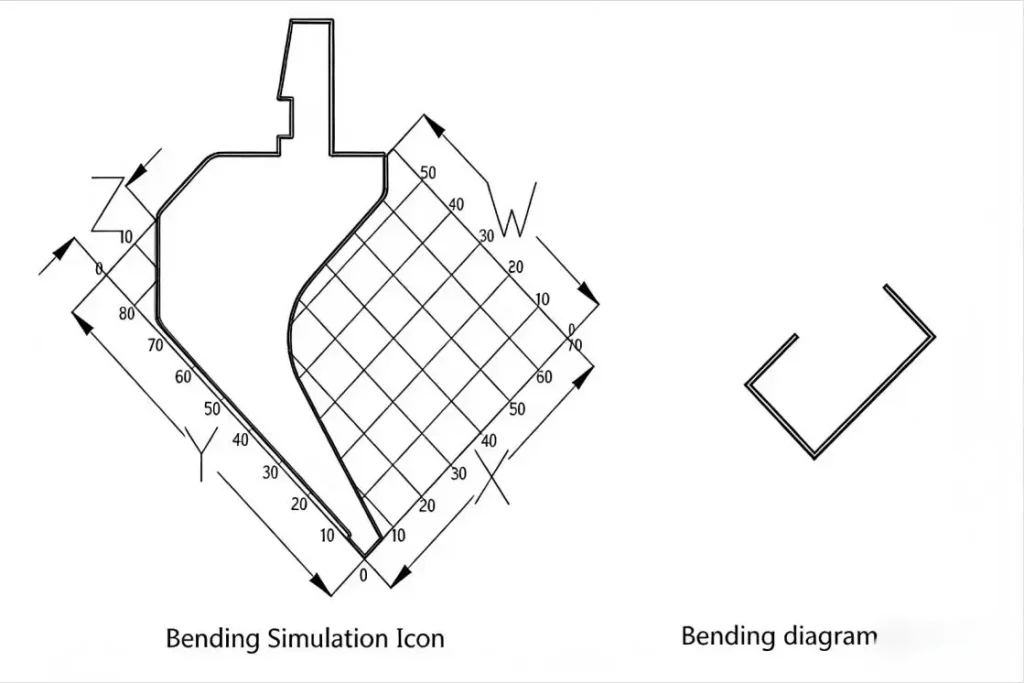
Bending knives manage clearance along the W direction. For the small bending knife, avoidance is reliable until X > 15 mm, and bending conditions are satisfied when Y > 30 mm. For the big bending knife, avoidance degrades when X > 25 mm, and bending conditions are satisfied when Y > 75 mm. These thresholds help planners choose the correct knife to prevent hitting the tool back during the stroke.
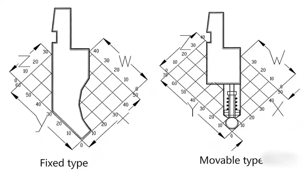
Arc knives, fixed or movable, enable consistent arc forming with a replacement round bar. A practical rule for die V-groove selection in arc jobs is the round bar diameter plus two times the plate thickness. This pairing stabilizes contact and spread, minimizing marks and flat spots at the tangent.
Special punches include offset and hemming options. Offset punches are available in integral lengths such as 415 mm and 835 mm. They form specified drawn shapes, but thick materials around T = 2.0 may show stronger indentation due to force concentration. Hemming punches flatten the edge after a pre-bend. When a dedicated hemming die is not available, a common bending die can be used, but the V-groove must be avoided to prevent imprint lines.


- Die and V-Groove Basics
Choosing the right die determines tonnage, springback control, and inside radius quality. For CNC Press Brake for Metal Fabrication, select V-grooves by thickness, material strength, and the radius needed. Go-to V openings are 4V, 6V, 7V, 8V, 10V, 12V, 16V, and 25V. Dies are typically 26 mm or 46 mm tall, affecting daylight, clearance, and backgauge range. Insert deep dies with 4V, 6V, 8V, et 12 grooves allow acute angles from 30° to 180° while preserving surface quality.
•Use single-body punches for precision. 415 mm and 835 mm cover general setups.
•Choose segmented sections (10 - 300 mm) for tight flanges and varied features.
•Pick V-openings in the 4V - 25V band to balance force and radius.
•Pick 26 mm or 46 mm die height to fit machine daylight and workpiece clearance.
•For arcs, set V groove from round bar diameter + 2T for smooth contact.
Practical Workflow and Pain Points Iin CNC Press Brake for Metal Fabrication
Many first-run defects come from sequence errors, poor backgauge alignment, or unsuitable tooling. JS RAGOS trains teams to validate each step before full production. L’objectif est simple: eliminate interference, stabilize angles, and minimize cumulative tolerance drift.
- L-Bend Setup Basics
L-bending is the most common operation and sets the foundation for Z and N sequences. Position with two backgauge fingers and keep the bend dimension on the same center line. For small flanges, reverse-position processing is often more stable. Acute angles need an insert deep die and an acute punch for a clean fold; 88° or 30° tip punches help reduce collision around holes or nuts.
•Align with two-point backgauge; avoid skew during the hit.
•Check interference between the punch and backgauge for very small sizes.
•If a hole is near the bend line or the edge size is less than half a V-groove, expect pull; adjust the method or pre-press the line with an 88° cutter.
•When small V slots cause expansion, first bend to a large angle with the small V, then finish with a normal die to stabilize size.
- Z-Bend Sequencing Made Simple
A Z-bend forms a reverse flange after an L-bend. Complete the L-bend at 89.5° - 90° to control springback. For the second hit, the workpiece and die must lie flat to avoid twist. Plan the sequence to minimize platform interference. If interference occurs, bend 1 to a larger angle first, then form bend 2, and finally pressurize bend 1 to target. This sequence protects surfaces and holds the gauge line.
•Create the L-bend initially; proceed with the counter-bend next.
•Validate platform clearance; if the bed/backgauge hinders, resequence.
•For acute Z-bends, first achieve 90°, then position depth 2, then depth 1.
- Managing Arc Bends
Arc forming can use a 90° die or a dedicated round bar with an arc knife. Some parts will not reach final geometry with a 90° die alone; a hand push or an 88° die can help bring the arc into tolerance. Use a detection fixture to check the arc chord and ensure the visual line matches the print. For 90° arcs, a simple selection rule is V = 2(R + T), which balances radius and material thickness.
Beyond sequence, beginners face surface marking and accumulated angle drift. Thick sheets around T = 2.0 tend to show stronger indentation. Use protective films, softer die radii, or wider V grooves to reduce marks. Avoid mixed tooling centers; confirm punch points lie on one line to protect angle consistency across stations.
Quality Control, Entretien, and JS RAGOS Support
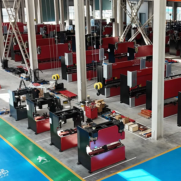
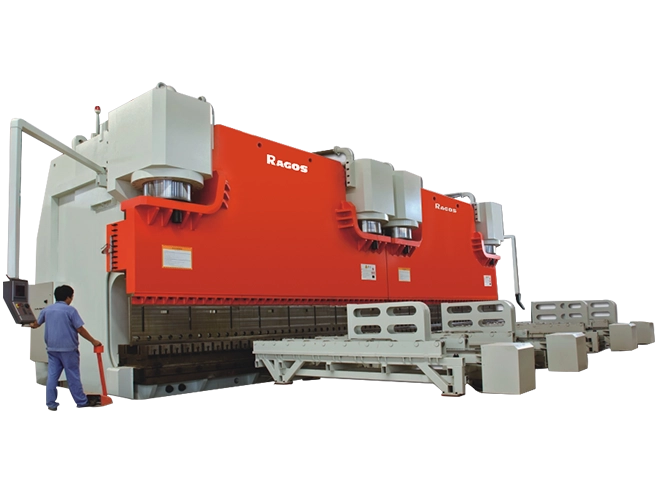
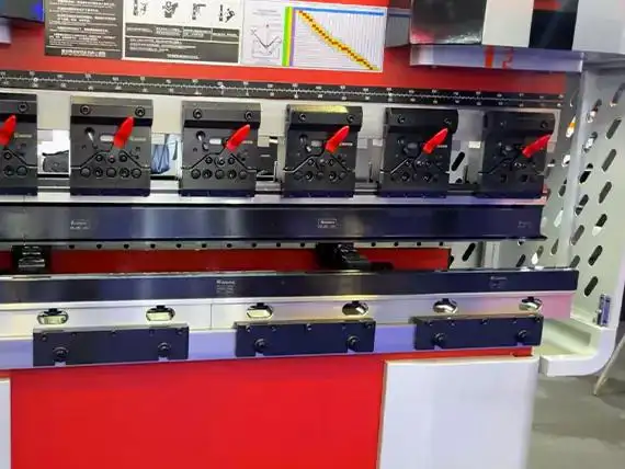
CNC Press Brake for Metal Fabrication demands consistent measurement and stable machines. JS RAGOS recommends first-article inspection on every new setup, along with daily gauge checks and scheduled calibration. Choose machines by bending width, Longueur, required pressure, available stations, and avoidance needs. Good layout reduces rework and scrap.
•Validate blank size at each process stage to keep errors from stacking.
•Re-zero backgauges; verify repeatability and stability prior to launch.
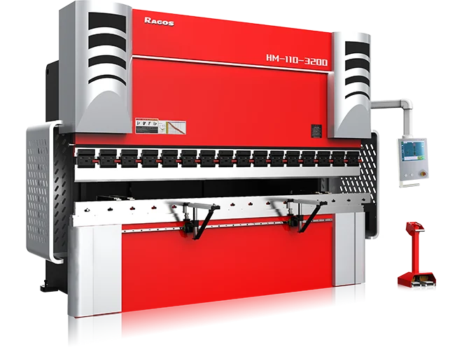
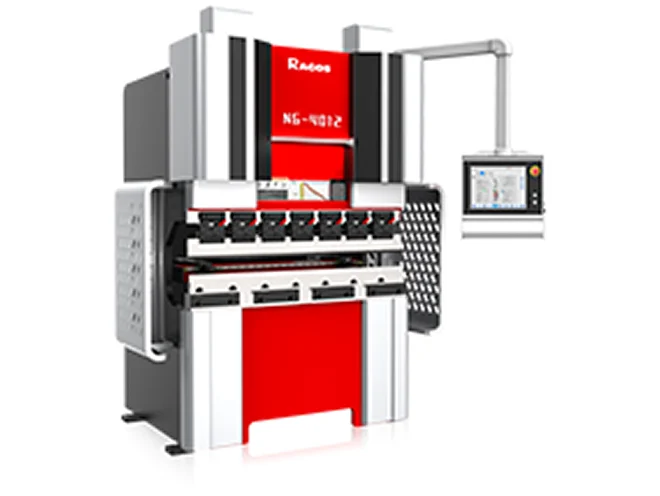
•Select a press brake by width, max length, tonnage, and clearance for tool/part avoidance.
•Run first-article inspection and monitor angles during the batch.
•Simplify layout: bend from inside to outside, small to large, and general to complex.
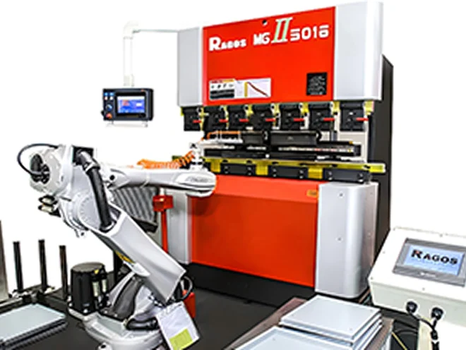
A careful method, paired with correct tooling, transforms throughput and quality. If your team is new to CNC Press Brake for Metal Fabrication, JS RAGOS can help. Our application engineers provide on-site training, bend simulations, and tooling audits. We tailor the punch - die setup, validate bend sequencing, and protect finish quality on your actual shop-floor builds.
Call to action: Partner with JS RAGOS to schedule a live demo, request sample bends with your materials, or book a tooling review. We’ll outline a clear ramp plan, limit iterations, and accelerate right-first-time results.